Your Compounder of Choice

Mon - Fri: 8:00 - 16:30 | Sat & Sun: Closed

How Does Injection Molding Work in 2026?

Injection molding remains one of the most important ways to manufacture precise plastic parts at scale. In 2026, its role extends from automotive dashboards and medical housings to appliance components and recyclable packaging. The process looks simple from outside. Heated polymer enters a metal mold, cools, and becomes a finished part. The details are less forgiving.

The 2024 Fortune Business Insights report valued the global injection molding machine market at approximately USD 15.29 billion in 2023. It projects growth to about USD 21.48 billion by 2032. That expansion reflects demand for automation, lightweight parts, shorter cycles, and tighter quality control. PlasticsEurope’s Plastics—The Fast Facts 2024 reported global plastics production of about 413.8 million tonnes in 2023. However, this figure covers many processes, not injection molding alone. That distinction matters.

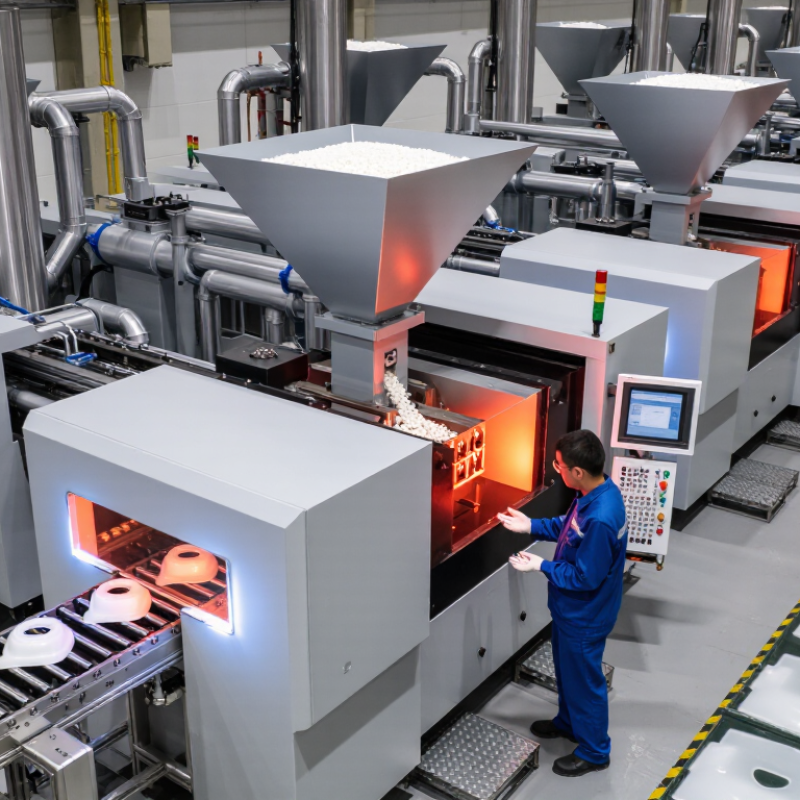
So, how does injection molding work in a real factory? A technician dries resin pellets, loads them into a hopper, and monitors barrel temperatures across several heating zones. A rotating screw then melts and meters the material. Hydraulic or electric force pushes it into a clamped mold, often under considerable pressure. Cooling channels remove heat before the mold opens and ejector pins release the part. Small changes can create large defects. Warpage, sink marks, flash, and trapped air still challenge experienced teams. Software helps, but it does not replace judgment. Energy use, recycled-content consistency, mold maintenance, and process validation require careful decisions in 2026. This guide examines each stage, while acknowledging an important limitation: no single machine setting suits every polymer, mold, or production target.

How Does Injection Molding Work in 2026?

Injection Molding: Definition, Purpose, and Core Principles

How Does Injection Molding Work in 2026?

Injection Molding: Definition, Purpose, and Core Principles

Injection molding is a manufacturing process that converts heated plastic pellets into shaped parts. A machine melts the material and pushes it into a closed mold under controlled pressure. The mold gives the part its dimensions, surface texture, and functional features. After cooling, the mold opens, and ejector pins release the finished component. It sounds simple. It is not.

The process serves high-volume production because one mold can create thousands of consistent parts. Operators monitor melt temperature, injection speed, holding pressure, cooling time, and mold temperature. Each setting affects shrinkage, strength, appearance, and cycle time. In 2026, connected sensors can record these conditions during every cycle. Engineers use the data to detect drift before defects become expensive. Still, software cannot replace sound mold design or careful material selection.

Core principles include flow, pressure, heat transfer, and dimensional control. The plastic must fill narrow ribs without trapping air or producing weld lines. Cooling channels should remove heat evenly, since uneven cooling can warp a part. Recycled or bio-based materials may reduce environmental impact, but they can require different processing conditions. This point deserves caution. A strong-looking prototype may fail after repeated heat or chemical exposure. Reliable production depends on testing, documented settings, and honest review of what the process cannot guarantee.

Machine Components and Their Roles in the Molding Process

How Does Injection Molding Work in 2026?

Machine Components and Their Roles in the Molding Process

In 2026, injection molding still depends on coordinated mechanical control. Each machine component affects part quality, cycle time, and material stability. Plastic pellets enter through the hopper and move into the heated barrel. Heater bands soften the material while a rotating screw mixes and transports it. The screw also measures the shot size before injection. A non-return valve prevents molten plastic from flowing backward. Small timing errors can still create visible defects.

The clamping unit holds the mold halves together during injection. Its moving platen must provide enough force to resist internal pressure. Guide pillars help keep both halves aligned. Inside the mold, the cavity forms the product’s outer shape. Core features create holes, ribs, and internal spaces. Cooling channels remove heat through circulating fluid. Uneven cooling may cause warping or sink marks. It happens more often than designers expect.

The nozzle connects the barrel to the mold’s sprue or runner system. It controls how molten plastic enters the cavity. After cooling, ejector pins release the finished part. Servo drives can adjust screw movement and clamp positioning with fine accuracy. Sensors monitor pressure, temperature, position, and cycle time. A controller compares these readings with selected process limits. Operators should still inspect samples, because sensors cannot detect every cosmetic issue. A stable setting can drift when material moisture, mold temperature, or room conditions change. That is where practical experience matters.

Step-by-Step: From Plastic Pellets to a Finished Part

How Does Injection Molding Work in 2026?

Step-by-Step: From Plastic Pellets to a Finished Part

Injection molding begins with small plastic pellets. Operators select the material for strength, flexibility, heat resistance, or appearance. The pellets may need drying before processing. Moisture can cause bubbles, weak surfaces, or cloudy marks. This step looks simple, but it often decides part quality.

A heated barrel melts the pellets gradually. Inside, a rotating screw carries the material forward and mixes it evenly. Sensors track temperature, pressure, and screw position. The mold then closes under controlled clamping force. The screw pushes a measured shot through a narrow nozzle and into the mold cavities. Plastic fills thin ribs, corners, and textured surfaces. Fast filling can create burns or trapped air. Slow filling may leave incomplete sections.

The machine holds pressure briefly while the plastic shrinks. Cooling channels remove heat through the mold steel. After solidification, ejector pins release the finished part. Workers or automated systems inspect dimensions, edges, color, and surface defects. Some lines also record process data for traceability and maintenance planning. Real production is less tidy than a textbook diagram. Material batches vary, cooling may be uneven, and a perfect setting can fail after a mold change. Experienced technicians review these details instead of trusting one number. A careful adjustment of temperature, pressure, or cooling time can prevent repeated defects. Then the cycle starts again.

Material Selection, Mold Design, and Process Control

How Does Injection Molding Work in 2026?

Material Selection, Mold Design, and Process Control

Injection molding begins with a practical material decision, not a machine setting. Engineers compare strength, heat resistance, shrinkage, moisture sensitivity, and recycled content. A resin may perform well in testing but fail after repeated thermal cycles. That gap deserves attention. Drying conditions must match the material supplier’s technical data. Small moisture levels can create bubbles, brittle surfaces, or inconsistent dimensions. Operators should record batch details, drying time, and barrel temperature for every production run.

Mold design controls how reliably the part fills and cools. Gate location affects weld lines, packing pressure, and visible surface quality. Cooling channels should follow the part’s thicker areas, where heat leaves more slowly. Poor cooling creates warpage that no later adjustment can fully repair. Engineers now use flow analysis and temperature sensors to identify risks before cutting steel. Still, simulation is not a physical trial. A first mold test often reveals assumptions that looked reasonable on screen.

Process control turns these decisions into repeatable production. Important variables include injection speed, pressure, screw recovery, mold temperature, and cooling time. Modern systems can monitor pressure curves and detect unusual changes during each shot. Human review remains necessary. Sensors can drift, and a stable number may hide a developing defect. Experienced technicians inspect sample parts, compare measurements, and adjust one variable at a time. That discipline feels slow, but uncontrolled changes make the real cause difficult to find.

How Does Injection Molding Work in 2026? - Material Selection, Mold Design, and Process Control

Typical engineering values for conventional thermoplastic injection molding. Actual settings depend on the resin grade, part geometry, mold construction, machine capability, and quality requirements.
Process Area Material or Design Variable Typical Data or Recommended Range Why It Matters Practical Control Method
Material Selection Polypropylene (PP) Melt: 200–250°C
Typical mold temperature: 20–60°C
Typical shrinkage: 1.0–2.5%
Low density, good chemical resistance, and relatively easy processing make PP suitable for containers, hinges, and general-purpose components. Control melt temperature, filling speed, and packing pressure to reduce sink marks and dimensional variation.
Material Selection Acrylonitrile Butadiene Styrene (ABS) Melt: 220–260°C
Typical mold temperature: 40–80°C
Typical shrinkage: 0.4–0.8%
Provides a useful balance of toughness, stiffness, surface quality, and dimensional stability. Dry moisture-sensitive grades before molding and use a sufficiently warm mold to improve surface appearance.
Material Selection Polycarbonate (PC) Melt: 280–320°C
Typical mold temperature: 80–120°C
Typical shrinkage: 0.5–0.7%
Offers high impact strength and heat resistance, but requires careful drying and higher processing temperatures. Use thoroughly dried pellets, controlled residence time, and a hot enough mold to limit molded-in stress.
Material Selection Polyamide 6 (PA6) Melt: 240–280°C
Typical mold temperature: 60–90°C
Typical shrinkage: 0.7–2.0%
Provides good strength and wear resistance; dimensional behavior is affected by moisture absorption and glass-fiber content. Dry pellets before use and condition finished parts when dimensional requirements account for moisture uptake.
Material Selection Polyoxymethylene (POM) Melt: 190–230°C
Typical mold temperature: 60–100°C
Typical shrinkage: 1.5–2.5%
Has low friction, good fatigue resistance, and excellent dimensional performance in moving components. Avoid excessive residence time and overheating; provide adequate venting to prevent degradation-related defects.
Material Selection Polyethylene (HDPE) Melt: 180–240°C
Typical mold temperature: 20–60°C
Typical shrinkage: 1.5–3.0%
Provides chemical resistance, toughness, and low moisture absorption, but usually has relatively high shrinkage. Use balanced packing and cooling, especially around thick sections and changes in wall thickness.
Material Preparation Moisture control Hygroscopic materials such as PC, PA, PET, and some TPU grades commonly require drying before molding. Moisture can cause splay, bubbles, hydrolytic degradation, reduced strength, and inconsistent viscosity. Follow the resin supplier’s drying temperature and time; verify moisture with a calibrated moisture analyzer when required.
Mold Design Nominal wall thickness Common general-purpose range: 1.5–3.0 mm
Keep thickness as uniform as practical.
Uniform walls reduce differential cooling, sink marks, warpage, and excessive cycle time. Use ribs, bosses, or structural features instead of adding large solid masses of material.
Mold Design Draft angle Typical starting point: 0.5–1° per side
Use more for textured surfaces or deep features.
Draft allows the part to release from the cavity without scuffing, drag marks, or excessive ejection force. Increase draft for deep walls, textured finishes, tight shutoffs, and materials with higher shrinkage.
Mold Design Rib thickness Common guideline: 40–60% of the adjoining wall thickness Thick ribs can create sink marks on the opposite surface and can concentrate residual stress. Use multiple thinner ribs with suitable radii rather than one oversized rib.
Mold Design Corner radii Use internal radii whenever possible; a common starting ratio is 0.25–0.50 × wall thickness. Rounded corners improve melt flow, reduce stress concentration, and lower the risk of cracking. Avoid sharp internal corners and verify radii against tooling, appearance, and assembly requirements.
Mold Design Gate location Place gates in thicker sections where possible; avoid critical cosmetic or high-stress areas. Gate position controls weld-line location, fiber orientation, filling balance, packing effectiveness, and visible gate marks. Use mold-flow analysis for complex parts and confirm the gate design with short-shot trials.
Mold Design Runner and gate type Cold runners are simple and economical; hot runners reduce runner waste but add thermal and maintenance complexity. The runner system affects pressure loss, material waste, cycle time, color changes, and process stability. Size runners and gates to support complete filling and packing without excessive shear or premature freezing.
Mold Design Venting Typical vent depth for many general-purpose thermoplastics: approximately 0.02–0.05 mm; confirm by material grade. Proper vents allow trapped air and gases to escape, reducing burns, short shots, weld-line weakness, and injection pressure. Vent at end-of-fill areas, parting lines, inserts, and deep ribs; clean vents during preventive maintenance.
Mold Design Cooling-channel layout Keep cooling channels consistently spaced from the cavity surface; use conformal cooling when justified by geometry and tooling cost. Cooling is often the longest part of the cycle and strongly affects warpage, shrinkage, and productivity. Monitor inlet and outlet temperatures, flow rate, and pressure drop for each cooling circuit.
Process Control Injection speed Often controlled in multiple stages rather than one constant speed; the correct value depends on flow length, wall thickness, and resin. Speed influences shear heating, weld lines, air entrapment, surface finish, and filling balance. Use a fill-time target and adjust speed profiles while monitoring peak pressure and part appearance.
Process Control V-to-P transfer Common starting point: transfer at approximately 95–99% full, before the cavity is completely packed. Consistent transfer prevents overpacking, flash, burn marks, and unstable part weight. Use screw position, cavity pressure, or a validated combined signal rather than relying only on operator judgment.
Process Control Pack and hold pressure Common starting range: 30–80% of peak injection pressure; validate through part weight and dimensional studies. Packing compensates for volumetric shrinkage while the gate remains open. Increase pressure or time only until part weight stabilizes; excessive packing can cause flash, stress, and difficult ejection.
Process Control Gate-seal time Determine experimentally, often by plotting part weight against additional hold time until weight no longer increases. Holding after gate freeze generally does not improve packing and may increase cycle time. Run a gate-seal study for each mold, material, and process window.
Process Control Cooling time Commonly ranges from 5–30 seconds for many small and medium thermoplastic parts, but varies substantially with wall thickness and resin. Insufficient cooling causes deformation during ejection; excessive cooling lowers productivity without proportional quality benefits. Optimize using ejection temperature, warpage measurements, cycle-time trials, and mold-temperature stability.
Process Control Cushion Typical starting target: 3–10 mm, depending on machine screw diameter and process requirements. A stable cushion helps maintain consistent packing pressure and indicates that the screw is not bottoming out during hold. Trend cushion position over time; investigate sudden changes for feeding, check-valve, leakage, or material issues.
Process Control Shot-to-shot repeatability Monitor part weight, fill time, peak pressure, cushion, melt temperature, and mold temperature. Stable process signatures help identify drift before defects become visible. Use statistical process control with defined control limits and documented reaction plans.
Quality Verification Common molded-part defects Short shot, flash, sink mark, warpage, weld line, burn mark, splay, void, jetting, and dimensional drift. Each defect can result from material condition, mold design, machine settings, cooling, venting, or handling. Change one variable at a time when diagnosing issues and record the relationship between settings and defect response.
Quality Verification Validation approach Use design review, mold trials, process-window studies, capability analysis, and first-article dimensional inspection. Validation demonstrates that the mold and process can repeatedly meet functional, dimensional, and cosmetic requirements. Document approved settings, material lot requirements, inspection criteria, maintenance intervals, and change-control rules.

Quality Inspection, Common Defects, and Modern 2026 Innovations

How Does Injection Molding Work in 2026?

Injection molding begins when heated polymer pellets enter a controlled barrel. A rotating screw melts and pushes the material into a closed mold. Pressure then holds the melt against cooling steel surfaces. After solidification, ejector pins release the finished part. Small changes matter. Melt temperature, injection speed, and cooling time can change dimensions within minutes.

Quality inspection now combines operator experience with digital measurement. Inspectors check weight, wall thickness, flash, sink marks, weld lines, burns, and short shots. Cameras can detect surface defects, but they may miss subtle warping under poor lighting. Coordinate measurement equipment verifies critical features, while process software tracks pressure and temperature trends. A reliable inspection plan samples parts during startup, steady production, and tool changes. I would not trust one perfect sample. It can hide unstable production.

Tips: Keep inspection records beside the machine. Compare the first ten parts with approved dimensions. Check mold vents when burns appear. Reduce speed carefully when flash develops. Modern 2026 systems use predictive sensors, automated vision, recyclable materials, and adaptive process control. These tools can reduce waste and respond to pressure drift. Still, automation is not judgment. Operators must question unusual readings, because a clean dashboard can reflect a poorly placed sensor. Some defects remain difficult to diagnose, especially when material moisture and ambient temperature change together.